Boundary Conditions in OSIRIS simulations
OSIRIS supports several different boundary conditions for fields and particles. This section provides a general description of how these boundary conditions work. To learn more about setting specific boundary conditions for your simulation check the following sections in the reference guide: node_conf, emf_bound, and spe_bound.
Global simulation boundary conditions
Periodic boundary conditions
OSIRIS can use periodic boundary conditions in any / all directions in your simulation, except for the radial coordinate in cylindrical geometry simulations. When using these boundary conditions the code behaves as if upper and lower boundaries are connected: all particles or waves exiting the lower / upper boundary will enter the upper / lower boundary. Periodic boundary conditions have specific implications in terms of the parallelization of the code: the neighboring node on a periodic boundary edge will be the node on the far side of the simulation box, and the code just behaves as it does when communicating between adjacent nodes.
Periodic boundaries are set globally on the node_conf section and override all other boundary conditions that may be specified in the input file. See the corresponding section in the reference guide for details.
Axial boundary conditions
When running in 2D cylindrical geometry, the lower boundary in the radial direction must be set to the “axial” type for EM fields and all particle species. This is a special type of boundary condition that handles the boundary at the symmetry axis. This is set automatically by the code, if the user tries to override this OSIRIS will issue an error and stop.
Boundary conditions for fields
Open-space
Open-space boundary conditions (also known as absorbing boundary conditions, or ABCs) are a type of boundary conditions that simulate an open-space boundary, i.e. they (attempt to) absorb all incident waves. OSIRIS supports two types of open space boundary conditions, perfectly matched layers (or PMLs) and Lindman:
- PMLs use Vay’s hybrid algorithm and are usually recommended, as they generally present better absorption properties and allow for adjacent absorbing walls. These can be selected using the “vpml” or “open” option in the emf_bound section of the input file.
- Lindmann boundary conditions are kept mostly for comparison with older simulations. They can be selected using the “lindmann” option in the emf_bound section of the input file.
Please check the emf_bound section of the reference guide for instructions on how to set open-space boundary conditions.
Open-space BCs for fields should be used together with open or thermal boundary conditions for particle species, however, OSIRIS allows users to choose any boundary condition for species. Please check the spe_bound section of the reference guide for instructions on how to set the particle species boundary conditions.
Note that if your simulation setup has plasma going all the way to the edge of the simulation box, choosing an open-space boundary for the fields will simulate a plasma-vacuum interface, which leads to the reflection of EM waves at this position.
Perfect Electric Conductor / Conducting
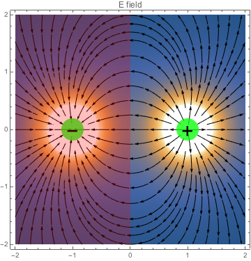
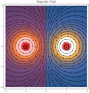
Perfect Electric Conductor boundary conditions (also known as PEC, or simply as conducting boundary conditions) simulate a boundary connecting to an infinite (electric) conductivity medium. PEC boundary conditions are generally used to model a conducting material boundary such as a waveguide. This situation can also be thought of as, for every charge creating the fields in the simulation, having a mirror charge of opposite value inside the conductor at the same distance from the boundary.
PEC boundary conditions may be defined by the following equations:
$\mathbf{n} \times \mathbf{E} = \mathbf{n} \cdot \mathbf{B} = 0$
where $\mathbf{n}$ is the boundary surface normal, and $\mathbf{E}$ and $\mathbf{B}$ are the electric and magnetic fields. If $r$ is the distance to the boundary this yields:
| E field | B field |
|---|---|
| $E_\parallel(-r) = -E_\parallel(+r)$ | $B_\parallel(-r) = B_\parallel(+r)$ |
| $E_\parallel(0) = 0$ | $B_\perp(-r) = -B_\perp(+r)$ |
| $E_\perp(-r) = E_\perp(+r)$ | $B_\perp(0) = 0$ |
To illustrate this behavior, the following two images show the electric and magnetic field for a single charge close to a PEC boundary located to the left of $x = 0$:
| Electric field | Magnetic field |
|---|---|
 |
 |
PEC boundary conditions should be used in connection with reflecting boundary conditions for particles. Users should also note that setting PEC boundary conditions will also force reflecting boundary conditions for electric currents, which means that all current that is deposited out of the simulation box inside the boundary will be folded back into simulation space.
To specify PEC boundary conditions you should use the “pec” or “conducting” options in the emf_bound section of the input file. See the corresponding reference guide section for details.
Perfect Magnetic Conductor / Reflecting
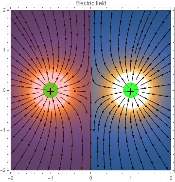
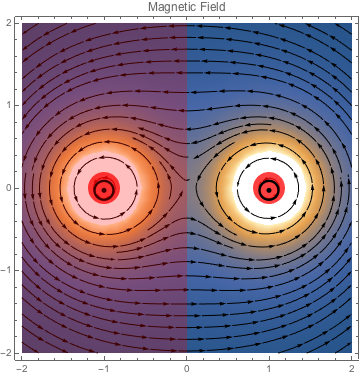
Perfect Magnetic Conductor boundary conditions (also known as PMC, or simply as reflecting boundary conditions) simulate a boundary connecting to an infinite (magnetic) conductivity medium. PMC boundaries are commonly used to model situations where the simulation setup is symmetric with regard to some plane (where the boundary is then defined), such as the collision between two identical plasma slabs. This situation can be thought of as, for every charge creating the fields in the simulation, having a mirror charge of the same value inside the conductor at the same distance from the boundary.
These boundary conditions may be defined by the following equations:
$\mathbf{n} \times \mathbf{B} = 0$, $\mathbf{n} \cdot \mathbf{E} = 0$
where $\mathbf{n}$ is the boundary surface normal, and $\mathbf{E}$ and $\mathbf{B}$ are the electric and magnetic fields. If $r$ is the distance to the boundary this yields:
| E field | B field |
|---|---|
| $E_\perp(-r) = -E_\perp(+r)$ | $B_\parallel(-r) = -B_\parallel(+r)$ |
| $E_\perp(0) = 0$ | $B_\parallel(0) = 0$ |
| $E_\parallel(-r) = E_\parallel(+r)$ | $B_\perp(-r) = B_\perp(+r)$ |
To illustrate this behavior, the following two images show the electric and magnetic field for a single charge moving towards the screen close to a PMC boundary located to the left of $x = 0$:
| Electric Field | Magnetic Field |
|---|---|
 |
 |
PMC boundary conditions should be used in connection with reflecting boundary conditions for particles. Users should also note that setting PMC boundary conditions will also force reflecting boundary conditions for electric currents, which means that all current that is deposited out of the simulation box inside the boundary will be folded back into simulation space.
To specify PMC boundary conditions you should use the “pmc” or “reflecting” options in the emf_bound section of the input file. See the corresponding reference guide section for details.
Boundary conditions for Particle species
Open-space / Absorbing
Open-space boundary conditions for particles (also known as absorbing) implement a simple particle absorption boundary condition for particles: particles leaving the simulation box through the boundary simply get removed from the simulation. To specify open-space boundary conditions for a given particle species you should use the “open” or “absorbing” options in the appropriate spe_bound section of the input file. See the corresponding reference guide section for details.
Open-space boundary conditions for particles are generally used together with open-space boundary conditions for the fields, see the corresponding reference guide section for details.
Reflecting
Reflecting boundary conditions for particles (also known as specular) implement a specular reflecting boundary for particles, particles will be reflected off the simulation boundary as if they suffered an elastic collision with an infinitely massive wall. To specify reflecting boundary conditions for a given particle species you should use the “specular” or “reflecting” options in the appropriate spe_bound section of the input file. See the corresponding reference guide section for details.
Reflecting boundary conditions for particles should be used together with conducting or reflecting boundary conditions for the fields, see the corresponding reference guide section for details.
Note that when a particle is reflected, this motion by itself does not deposit any electric current. If the user specified a conducting or reflecting field boundary condition then the electric current will be automatically folded back into the simulation box, accurately calculating the current deposition from the reflection, even for higher order interpolation levels.
Thermal bath
Thermal bath boundary conditions for particles will absorb any particle exiting through the boundary and re-emit a particle into the simulation box with the same charge and momentum taken from a user-specified distribution. These boundary conditions are commonly used to model scenarios where a warm (hot) plasma exists near the simulation box edge maintaining particle density and temperature at the boundary.
The user may choose from several types of thermal distributions, including asymmetric distributions. To specify reflecting boundary conditions for a given particle species you should use the “thermal” option in the appropriate spe_bound section of the input file. See the corresponding reference guide section for details. Reflecting boundary conditions for particles should be used together with open-space, conducting or reflecting boundary conditions for the fields, see the corresponding reference guide section for details.
Note that to minimize field growth at the simulation boundary, OSIRIS will also deposit the electric current from the motion of the re-injected particle coming into the simulation box.